
The frequency inverter for the air unit presents a unique project challenge: integrating the inverter directly with the electric motor. This design choice minimizes installation in the field, as the inverter comes pre-attached the motor. Inside the air conditioning unit, the key challenges included ensuring minimal disruption to the airflow and effectively dissipating the heat generated by the inverter, which had increased significantly due to its close coupling with the motor.


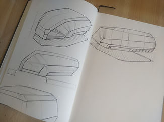


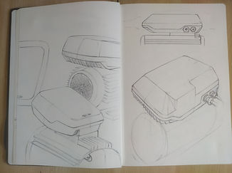
Alternatives:
The solution for heat dissipation was to use the motor coupling component itself as a heat sink, which was injection-molded in aluminum. The air flow from the climate control system was also utilized, being directed through the heat sink fins. Additionally, a more organic shape was chosen, featuring a droplet-like profile, in order to generate as little drag as possible in the air flow.

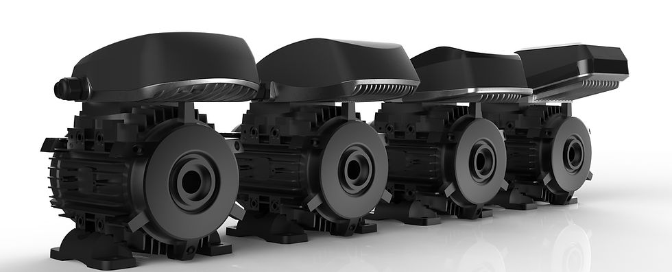
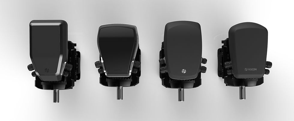


The image below demonstrates the airflow passing through the fins, where it exchanges heat with the microprocessor area. The air is then directed to exit through the sides, diverting away from the assembled motor + frequency inverter unit.


